“I’ve played with the techniques mentioned. However, I can’t seem to find the way to insert an image onto the line as suggested in the article. Can you please elaborate?”

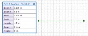
Now enter a height of .175” into the Size & Position box. This represents 1RU (Rack Unit) at 1/10 scale.

Enter height of .175"
Select the shape and Group it using the Shape menu. This places a group around the line and the group defaults to 2D behavior.

Grouped shape
Convert it to 1d using the menu Format > Behavior and check Line 1D for the Interaction style.

Select 1D in the Behavior box
You now have a line contained within a group that is 1D. However, the endpoints of the 1D shape are at the midpoints of the left and right sides. In fact, the grouped shape now looks exactly like the ungrouped 1D line shape with height. Let’s place more geometry into it. Select Edit > Open Group. You now have a place to draw that’s inside the group:

Open the Group to draw within it
We’ll add several simple boxes and delete the original line:

Add geometry to the group
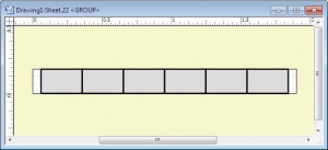
When we close the Group window, we can see the image inside the group.

Grouped shape with image
The last step is to move the 1D endpoints down to the lower left and right corners of the shape so that the shape snaps properly onto a rack. To do this, open the ShapeSheet with the menu Window > Open ShapeSheet. Click on the LocPinY cell and enter “0” then close the ShapeSheet. The result is a 1D shape that will snap into a rack properly.

- Shape in a rack
At Visimation where we produced thousands of network equipment shapes, we have automation programs that perform similar steps, as well as many other behavioral modifications, on a device drawing. The result is a Visio equipment shape that eases the drawing process and looks great. Again, you can download free equipment shapes at our ShapeSource online store.
© 2010, Visimation. All rights reserved.
I love this tutorial, really useful for making rack equipment shapes. I was having difficulty figuring out how to apply the 1D shape ‘handles’ (?) to the bottom so that it aligned properly in the rack, but this tutorial made it easy.
I did experience one issue, when going to resize the shape, it expands on the X plane, but doesn’t keep the ratio in the Y plane, even though I’ve set the Protection on the Aspect Ratio. The shape in question is a metafile, as described in another tutorial on this site.
Yes, Visio 1D shapes don’t seem to obey aspect ratio protection as one would expect. To force it into the behavior you want, you need a ShapeSheet formula. I may need to post an article about this since pictures would help but let’s see if I can explain this clearly enough in words.
BTW, keep in mind that Microsoft’s original spec for Visio equipment shapes was that they would be at a scale of 1:10. So, if you drop a shape that complies with this spec onto an unscaled Visio page, a 19″ wide device will show as 1.9″ in “length” because it’s a 1D shape. I’ll assume we’re working with this kind of device shape.
I’m going to explain how to lock the ratio of width to height, so first, calculate the ratio of width to height of your device. For a 1RU device it would be 1.75″/19″=.092. Open the ShapeSheet for your device shape. In the Shape Transform section, in the Height cell, enter “GUARD(Width*.092)”. This will set the Height as a function of the width. Now, when you drag a 1D endpoint the aspect ratio will remain constant.
Worked like a charm!
Many thanks for this info. I’ve searched the web for several days to find out how to do this. Your tutorial is great.
This was a very helpful post! Thank you.
Great little article.
Helped me do exactly what I needed with the rack and I did not know about the OPEN GROUP as opposed to UNGROUP
Absolutely a great article. For those using Visio 2010, in order to convert to 1d you will need to enable the developer tab under “customize ribbon”, since the “Behavior” option has moved out of the menu format options. Do a search for “What Happened to the Behavior Dialog in Visio 2010?” for more detail.
This is a GREAT article! Thank you very much. I’ve been building rack diagrams and we use some components for which manufacturer stencils are not available. I take photos and then try to convert to stencils, but I couldn’t get them to ‘latch onto’ the rack connectors.
One issue I had was in the step where you say “We’ll add several simple boxes and delete the original line”. Whenever I deleted the line, it killed my group. I ended up formatting the line to use a pattern of NONE, but there’s obviously still space allocated for the line. What am I missing?
I think you may be missing a couple of important factors. After you draw the line, size it to 1.9″ long, and then Group it, you have a group with just that line inside of it. It’s the group that you will be modifying to create the 1D behavior you want. When you delete the line, you must be in the “Open Group” mode so that you are essentially working inside the group envelope. In that state, deleting the line only affects the geometry inside the group, not the group’s behavior at all.
By the way, in case you want to try this, I just went through the exercise of inserting an image into the group instead of drawn geometry. If you insert, say, a 1U Cisco 3750 image when you are inside the group, you can resize it to fit properly. First, select the image and set it’s protection on for aspect ratio. Then, move the shape handles so that it’s about 1.75″ wide if it has no mounting ears, and 1.9″ if it does have ears. Close the group and perform the described operation to open the group’s ShapeSheet and set the LocPinY cell to 0″. Now you have a realistic image inside the group and the shape will snap into a rack. I also suggest that you open the Group Behavior dialog again as shown in the article, and set the Selection field at the lower right to “Group only”. This will prevent you from accidentally “sub selecting” the image inside of the group and moving it out of position. Note that the contents of a group can be moved outside of the boundaries of the group envelope… which you typically don’t want to do although there are exceptions.
This is a good technique for creating a shape in an emergency if you can get the image from the web. However, shapes with pixel images in them will not perform as well as those drawn in Visio geometry and converted to metafiles as we do (that’s another topic).
These steps are perfect and very easy to follow. However, they seem to only really work with rectangles and squares. I have an elliptical shape that has no corners and won’t work well with corner or central anchor points. Is there a tutorial about how to anchor non-rectangular stencils in Visio?
I’m not clear on what you are trying to do. You can insert an image of any type into the group as described here but if you want the line’s endpoints to appear at a certain location on a non-rectilinear object, we’d need to understand what the object is and how you want it to behave. Feel free to send an explanatory image and question to info@visimation.com if you would like us to take a look at the specific task you are trying to address.
For those visio 2010 and after having issues finding the “Group behavior” this link should help. http://packetlife.net/blog/2010/aug/27/what-happened-behavior-dialog-visio-2010/
Everything is working great, except, if I move the rack to the left, your shapes retain their original shape. Mine stays connected on the left side, and just stretches. I’ve compared all settings in Behavior, Protection, and the shape sheet, can’t find the culprit.
Apologies for the long delay. The notice of your comment did not arrive to me for some reason. If you would still like assistance with this, would you send us your drawing to analyze?